All particles have a fundamental property known as electrical charge, measured in coulomb. Charges are either positive or negative and two charged particles exert a force on other charges. Two like charges repel each other, and two unlike charges attract each other. More simply, a positively charged particle and a negatively charged particle experience a force pushing them towards each other. Charges are only measured in whole-number multiples of the fundamental unit columbs. A single electron carries a charge, and a proton carries a charge.
Electric charges produce an electric field . An electric field is defined as a vector field describing the force, , per unit of charge, , exerted on an infinitesimal positive charge at rest at any given point. Electric fields are visualized by field lines: arrows that point away from positive charges and toward negative ones. For RC circuits, we use a conservative, electrostatic (Coulomb) field. As a result the field is curl-free and path-independent, i.e., the work done moving a charge around any closed loop is zero. The field points along the wire from positive charge to negative charge.
Electric potential, denoted by , assigns a scalar (in volts, i.e., joules per coulomb) to every point in space. In electrostatic fields, it is given by the line integral
where is an arbitrary path from some fixed reference point to . The above integral describes the amount of work per unit charge needed to move a charge from to . Because is conservative (), the above integral does not depend on any specific path , but only its endpoints, i.e., if such that , then by the gradient theorem
Because is a fixed point, we get that
Voltage, also known as electrical potential difference, is the difference in electric potential between two points. That is,
where is an arbitrary path from to . Thus, describes the work needed per unit of charge to move a positive charge from to .
The actual rate at which charge flows through the electric field is called the electric current, measured in amperes, and is given by
where is the charge at a given point. Since charges travel from positive to negative, gives a measure of how many positive charges are passing a specific point. Combining voltage alongside current gives us which is the amount of work per second, or watts.
The flow of charges are impeded depending on the conductor. The amount of impedance is called electrical resistance and is measured in Ohms. In an ideal case,
where is the length of the conductor, is the cross-sectional area of the conductor, and is a constant known as the electrical resistivity dependent on the conductor material. Ohm’s law states that
Thus, the amount of work per unit charge to move charges through the conductor is directly proportional to the resistance. A perfect conductor () implies that zero voltage is required to move charges, that is, the voltage does not drop through the conductor. An insulator aims for , which results in describing zero flow of charges no matter how much voltage is applied.
RC Circuits
An RC circuit (or resistor-capacitor circuit) is an electric circuit composed of resistors and capacitors. A capacitor is a device that stores electrical energy energy (kilowatt-hours) comprised of two closely spaced plates that are insulated from each other. When hooked to a battery, electrons are pushed onto one plate resulting in a negative charge . These electrons are the result of electrons being stripped from the other plate, leaving a positive charge . As a result, the positive charges are attracted to the negatively charged plate generating an electrical field. Due to the plates being insulated from each other, the electrical field forms a loop pointing alongside the RC-circuit from the positively charged plate to the negatively charged plate.
The ability of a capacitance to store electrical charge is called capacitance and is measured (farads) by the change in charge in response to a difference in electric potential, i.e.,
Through the chain-rule we get the current-voltage relationship which states that the current leaving the capacitor is given by
Consider the following circuit:
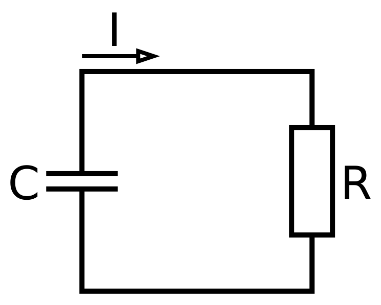
According to Kirchhoff’s current law, for any node of an electrical circuit the sum of currents flowing into that node is equal to the sum of currents flowing out of that node, that is,
where is the signed current entering the resistor, and is the signed current leaving the resistor. Using Ohm’s law for the term and applying the current-voltage relationship give us
a linear differential equation. Solving for gives us an exponential decay curve
where is the capacitor voltage at time .