Verilog is a widely used hardware description language (HDL) used for design and verification of digital systems and circuits. The language describes digital cirtcuits starting from the most basic elements such as logica gates, to more complex functional blocks and systems. While Verilog appears like a typical programming language, it is designed to model physical hardware and includes concurrent operation, signal timing, and electrical behavior. Due to the concurrent operations, there are two assignment operators:
- a blocking assignment (
=); and - a non-blocking assignment (
<=).
Below is a simple example of a circuit consisting of two flip-flops:
module circuit(clock, reset);
	input clock;
	input reset;

	reg flop1;
	reg flop2;

	always @ (posedge reset or posedge clock)
		if (reset)
			begin
				flop1 <= 0;
				flop2 <= 1;
			end
		else
			begin
				flop1 <= flop2;
				flop2 <= flop1;
			end
endmodule
The module consists of 5 main sections:
module circuit(clock, reset);Defines a new module named circuit that has two ports (inputs/outputs): clock and reset. The ports define how the module communicates with the outside world.
input clock;
input reset;
Defines our two ports as input ports. That is, the signals from ports clock and reset flow into our module.
reg flop1;
reg flop2;
Defines two single-bit variables used by the module. Note that while a single-bit register in hardware is implemented by flip-flops, these terms do not create any actual circuitry. They are just used as variables.
always @ (posedge reset or posedge clock)Defines a behavior block that runs anytime there is a rising edge (posedge) to the input reset or clock. In standard programming terms, one may think of it as defining a callback method that is ran whenever reset or clock changes from a 0 to a 1.
if (reset)
	begin
		flop1 <= 0;
		flop2 <= 1;
	end
else
	begin
		flop1 <= flop2;
		flop2 <= flop1;
	end
This defines the main logic of our circuit, which depends on the above behavior block. The begin/end keywords is Verilog’s way of defining block statements, i.e., Verilog’s form of {}. The circuit’s logic states that
- if
resetis high, then our variables are set to a specific state (flop1=0,flop2=1) - otherwise, the variables
flop1andflop2swap values.
Notice that we are using the non-blocking assignment (<=). If we used a blocking assignment, then like other programming languages flop1 would be updated before flop2, causing flop2 to not be changed. In non-blocking assignment, all right-hand sides are evaluated using the current values before any assignments are performed. In terms of C, one may think of it as the following:
bool cur_flop2 = flop2;
bool cur_flop1 = flop1;
flop1 = cur_flop2;
flop2 = cur_flop1;
In practice, one should use <= for clocked logic and = for combinational logic.
Below is more complex example of a 4-bit counter:
module counter(clk, reset, enable, count, tc);
	parameter WIDTH=4;  // How many bits
	input clk;
	input reset; // On high, resets the counter back to zero
	input enable; // If high, the counter increases by one each clock pulse
	output reg [WIDTH-1:0] count; // The counter value as a 4-bit bus
	output tc; // Flag indicating count has reached maximum value

	// Sequential logic:
	always @ (posedge clk) begin
		if (reset) // If reset is high, reset the count
			count <= 0;
		else if (enable) // If enable is high, increment count
			count <= count + 1; // Wraps on overflow
	end

	// Combinatorial logic: high when count is at maximum
	assign tc = enable & (count == {WIDTH{1'b1}});
endmodule
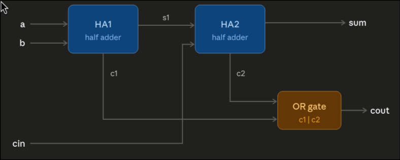
Verilog allows modules to instantiate other modules. One connects them to input/output via wires. Below is an example of a 3-bit adder showing this in action:
module half_adder(a, b, sum, carry);
	input a, b;
	output sum, carry;

	assign sum = a ^ b; // a XOR b
	assign carry = a & b; // a AND b
endmodule

module full_adder(a, b, cin, sum, cout);
	input a, b, cin;
	output sum, cout;

	wire s1, c1, c2; // Internal nets connecting submodules

	// Instantiate two half-adders:
	half_adder ha1( .a(a), .b(b), .sum(s1), .carry(c1) );
	half_adder ha2( .a(s1), .b(cin), .sum(sum), .carry(c2) );

	// Carry out if either half-adder generated a carry
	assign cout = c1 | c2;
endmodule
Visually, our full_adder module produces like the following circuit: